
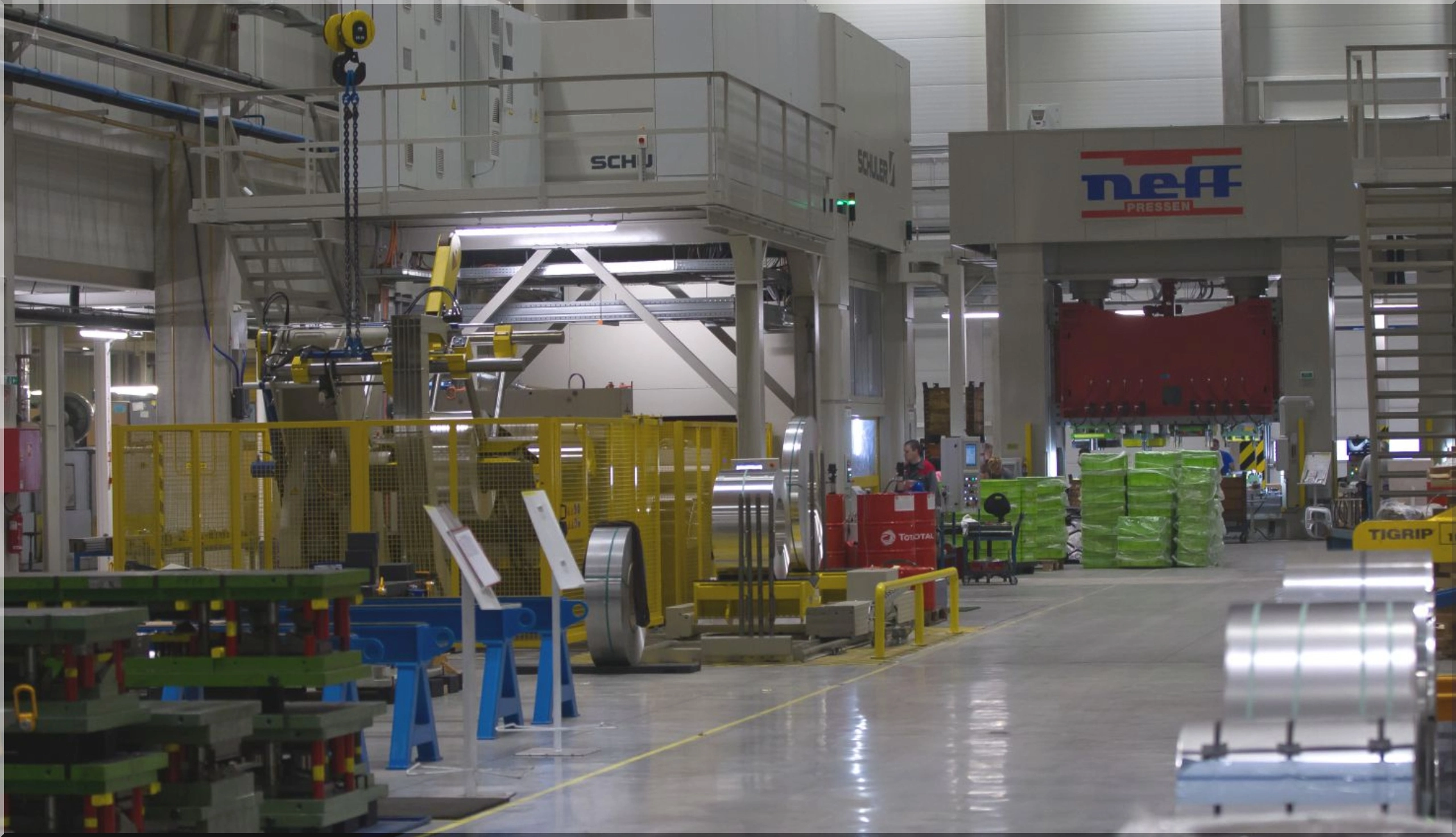
Sheet metal parts manufacturing sits at the intersection of speed, precision, and cost control. Whether the end product is a structural bracket, an enclosure, or a complex multi-stage stamped component, the process chosen to make it will shape everything downstream, from tolerances and surface finish to tooling investment and how quickly a design can move from prototype to volume production. For engineers and procurement teams evaluating options, understanding the trade-offs between cutting, forming, joining, and finishing methods is essential before a single quote is requested.
This guide walks through the core decisions involved in sheet metal parts manufacturing, from material and process selection to common failure points and supplier evaluation criteria, so that technical buyers can make informed choices rather than relying on a vendor's recommendation alone.
Understanding the Sheet Metal Manufacturing Workflow
Most sheet metal components pass through a sequence of distinct operations, even if a single supplier handles all of them under one roof:
- Material selection and coil or blank preparation: choosing gauge, alloy, and temper based on mechanical and corrosion requirements.
- Cutting: separating the blank from coil or sheet stock using laser, punch, or blanking dies.
- Forming: bending, stamping, or deep drawing the flat blank into a three-dimensional shape.
- Joining: welding, riveting, or fastening multiple formed pieces into an assembly.
- Surface treatment: degreasing, passivation, coating, or plating to meet corrosion or cosmetic requirements.
Each stage has its own tolerance stack-up and cost driver, and decisions made early, particularly around material and cutting method, constrain what's achievable later in the process.
Cutting Methods: Matching the Tool to the Job
The two dominant approaches for separating sheet metal are laser cutting and die-based blanking or punching. The choice between them is rarely about which is "better"; it's about volume, geometry, and lead time.
Laser Cutting
Laser cutting excels in low-to-mid volume production and prototyping because it requires no dedicated tooling. A part design can be sent directly from CAD to the cutting bed, making it ideal when designs are still evolving or when a wide variety of part geometries needs to be produced from the same material stock. The trade-off is per-part cost at high volumes, since cycle times are generally longer than a stamping press stroke.
Press Cutting and Blanking from Coil
For high-volume runs, cutting directly from coil using progressive dies is typically far more economical per piece. The upfront tooling cost is significant, but once amortized across tens of thousands of parts, the per-unit cost drops well below laser cutting. This approach also allows cutting and initial forming operations to be combined within a single die, reducing handling and cycle time. The downside is inflexibility: a design change after tooling is cut can be costly and slow to implement.
A practical rule of thumb: below roughly 1,000 to 5,000 units annually, laser or punch-press cutting on flat-bed equipment usually wins on total cost; above that threshold, dedicated die tooling tends to pay for itself.
Forming Processes and Press Selection
Once a part is cut, forming gives it its functional shape. The choice of press technology affects both part quality and what geometries are even possible.
- Mechanical presses deliver high speed and repeatability, well suited to simple, high-volume stamping where the stroke profile doesn't need to vary.
- Hydraulic presses offer adjustable force and full-stroke force capability, making them better suited to deep draws or thicker gauge material where mechanical presses might struggle.
- Servo-driven presses allow the stroke speed and force profile to be programmed and varied within a single cycle, which is valuable for difficult-to-form alloys or parts prone to springback, since the press can slow down precisely where the material needs it.
Springback, the tendency of formed metal to partially return toward its original shape after the forming force is released, is one of the most common sources of dimensional rework in sheet metal manufacturing. It varies by alloy, gauge, and bend radius, and is increasingly predicted in advance using forming simulation software rather than corrected through trial-and-error die adjustments. Designers who specify generous bend radii relative to material thickness, and who avoid features placed too close to a bend line, tend to see far fewer first-run dimensional issues.
Material Considerations That Affect Manufacturability
Not all sheet metals behave the same way under cutting and forming loads, and material choice has downstream effects on tooling life and part performance:
- Mild and high-strength steels are cost-effective and forming-friendly but require corrosion protection in exposed applications.
- Stainless steels resist corrosion well but work-harden faster, increasing tool wear and sometimes requiring lower forming speeds.
- Aluminum alloys offer a strong strength-to-weight ratio but have less forming forgiveness, since tighter bend radii increase cracking risk compared to steel of similar gauge.
Specifying material temper correctly matters as much as specifying the alloy. A temper that's too hard may resist forming or crack at bends; one that's too soft may not hold dimensional tolerance under load in the finished assembly.
Welding and Joining Multi-Piece Assemblies
Many sheet metal components are not single stampings but assemblies of several formed pieces joined together. Spot welding remains the standard for joining overlapping sheet sections quickly and with minimal heat distortion, making it common in body structures and brackets where multiple stamped pieces meet. Arc welding processes, including gas-shielded methods, are generally reserved for joints that need continuous, full-strength seams rather than discrete points, for example structural seams or components subject to higher mechanical or thermal load.
Choosing the wrong joining method for the application is a frequent and costly mistake: spot welds on a joint that needs continuous sealing will leak or fatigue prematurely, while full-seam arc welding on a part designed for spot joints can introduce unnecessary heat distortion and cost.
Surface Treatment and Corrosion Protection
Surface preparation is often treated as an afterthought, but it directly determines coating adhesion and long-term corrosion resistance. A typical sequence includes degreasing to remove forming lubricants, followed by chemical conversion or phosphating, and finally a coating or plating step appropriate to the operating environment. Skipping or rushing the degreasing stage is one of the most common causes of premature coating failure in the field, since residual oils prevent proper adhesion even when the coating itself is applied correctly.
Selecting a Manufacturing Partner: Key Evaluation Criteria
When evaluating a manufacturing partner for sheet metal parts, technical buyers should look beyond price quotes alone:
- Process breadth: does the supplier handle cutting, forming, welding, and finishing in-house, or will the part travel between multiple subcontractors, adding lead time and quality risk?
- Simulation capability: can the supplier model forming behavior and springback before cutting tooling, reducing costly trial iterations?
- Tooling expertise: for progressive die work, does the supplier design and build its own tooling, or outsource it, which can affect lead time and design flexibility?
- Quality control methods: what dimensional inspection and process control measures are used during production runs, not just at final inspection?
- Volume flexibility: can the same partner support a low-volume prototype run and then scale to full production without re-sourcing?
Readers wanting more detail on how cutting, forming, and welding stages are typically combined in practice can find further explanation of sheet metal parts manufacturing workflows as one reference point for how these stages interrelate in a production environment.
Common Mistakes That Drive Up Cost or Cause Delays
- Specifying tolerances tighter than the application actually requires, which forces unnecessary secondary operations.
- Designing bend radii too tight for the chosen material and gauge, leading to cracking or excessive springback correction.
- Treating tooling design as an afterthought rather than involving tooling engineers during part design, when changes are still cheap to make.
- Underestimating lead time for progressive die tooling when planning a production launch date.
- Choosing a joining method based on equipment availability rather than the joint's actual mechanical or sealing requirements.
Balancing Cost, Quality, and Lead Time
Sheet metal parts manufacturing involves a series of interlocking decisions: material, cutting method, forming technology, joining approach, and finishing, each of which affects cost, lead time, and final part quality. There is rarely a single "correct" process; the right combination depends on production volume, part geometry, and performance requirements. Buyers who understand these trade-offs, and who ask the right questions of a manufacturing partner before committing to tooling, are far better positioned to avoid costly rework and schedule delays later in the program.
Frequently Asked Questions
What volume justifies investing in dedicated stamping tooling?
As a general guideline, production runs above roughly 5,000 to 10,000 units annually often justify the upfront cost of progressive die tooling, since per-part costs drop significantly compared to laser cutting or punching at that scale. Lower volumes typically favor more flexible, toolless methods.
How is springback typically minimized in production?
Springback is most often addressed through forming simulation during the design phase, careful selection of bend radius relative to material gauge, and in some cases over-bending the die slightly to compensate for the material's elastic recovery.
Does material thickness limit which cutting method can be used?
Yes. Laser cutting has practical thickness limits that vary by laser power, while press cutting and blanking can handle thicker gauges but require proportionally higher tonnage and more robust tooling as thickness increases.
When is spot welding preferred over continuous arc welding?
Spot welding is generally preferred when joining overlapping sheet sections that don't require a continuous seal, since it introduces less heat distortion and is faster for high-volume assembly. Continuous arc welding is reserved for joints needing full-strength or sealed seams.
- 119 views